

FYT/FYN-H1/H2
Vane dampers
Bansbach vane dampers and dashpots are used to dampen drives, control speed, and many other applications. Our rotational viscous dampers are maintenance free and the most durable units on the market. Bansbach silicone oil viscous dampers are available in either fixed rate or adjustable models. On adjustable vane dampers adjustment is made with an integrated set screw.
The damping direction of the vane dampers with continuous rotation can be clockwise, counter clockwise, or in both directions. In vane dampers with continuous rotation, a fluid damping is produced by the shearing or braking force of silicon fluids resistance between the surfaces of a rotor and a stator. The damping moment is determined by the viscosity of the fluid and the size of the orifice or gap. The damping characteristics can be customized by changing the viscosity of the silicon fluid or by changing the structure of the rotor and stator. vane dampers life-cycles are typically in excess of 50,000 cycles. The service life may be significantly higher or lower, depending on the application. After extended life cycles the dampers still produce over approx. 80% of their original damping moment.
The damping direction of the vane dampers with continuous rotation can be clockwise, counter clockwise, or in both directions. In vane dampers with continuous rotation, a fluid damping is produced by the shearing or braking force of silicon fluids resistance between the surfaces of a rotor and a stator. The damping moment is determined by the viscosity of the fluid and the size of the orifice or gap. The damping characteristics can be customized by changing the viscosity of the silicon fluid or by changing the structure of the rotor and stator. vane dampers life-cycles are typically in excess of 50,000 cycles. The service life may be significantly higher or lower, depending on the application. After extended life cycles the dampers still produce over approx. 80% of their original damping moment.
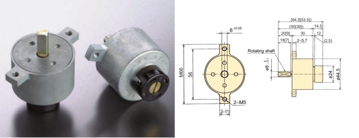
| Model | Max. torque | Reverse torque | Damping direction | Max. angle | Operating temperature | Weight | Body and cap material | Rotating shaft material | Oil type |
|---|---|---|---|---|---|---|---|---|---|
| FYT-H1(2)-104 | 10 Nm (100kgfcm) | ----- | Both directions | 105° | -5 ~ 50°C | H1: 240±10g, H2: 235±10g | Zinc die-cast (ZDC) | S25C | Silicone oil |
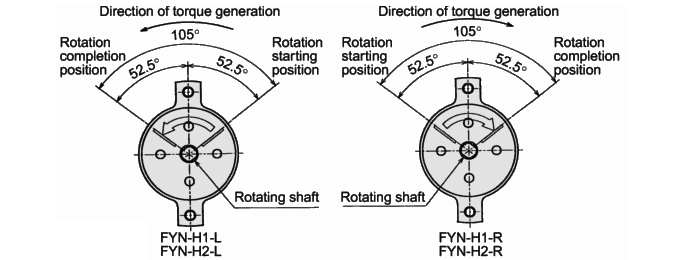
| FYN-H1(2)-R104 | 10 Nm (100kgfcm) | 0.5 Nm (5kgfcm) | Clockwise | ||||||
| FYN-H1(2)-L104 | Counter-clockwise |
| Damper characteristics vary according to the ambient temperature. In general, the damper characteristics become weaker as the temperature increases, and become stronger as the temperature decreases. This is because the viscosity of the oil inside the damper varies according to the temperature. When the temperature returns to normal, the damper characteristics will return to normal as well. The changes in the time it takes for the lid to close are shown in the graph to the right. | 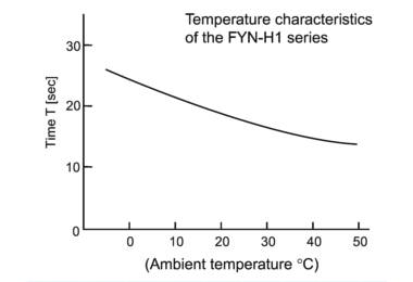 |
| The damper's working angle is ±52.5°with respect to the attachment flange, as shown below. Please determine where to attach it according to your needs. Also, rotating the damper beyond this angle will cause damage to the damper. Please ensure that an external stopper is in place. | |
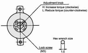
| In the FYT-H1 (H2) and FYN-H1 (H2) series, the amount of generated torque can be adjusted with the adjustment knob located towards the rear of the main body. Insert a screwdriver in the minus groove to turn. | 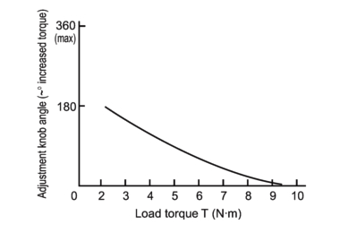 |
| Turn the adjustment knob in the H direction to increase torque. | |
| Turn the adjustment knob in the L direction to reduce torque. | |
| Do not turn the adjustment knob more than 360°. Turning the knob more than 360° causes the adjustment shaft to slip out, resulting in oil leakage. | |
| Once the adjustment is complete, secure with a lock screw. Using the damper without securing it may result in fluctuating torque. | |
 | |
 | |